CNC from Screenprinter - Part 5
CNC ·Spindle and ballscrew coupling
In this part of the series, the spindle and the coupling of the two ballscrews on the y-axis are described. Find the previous part here.
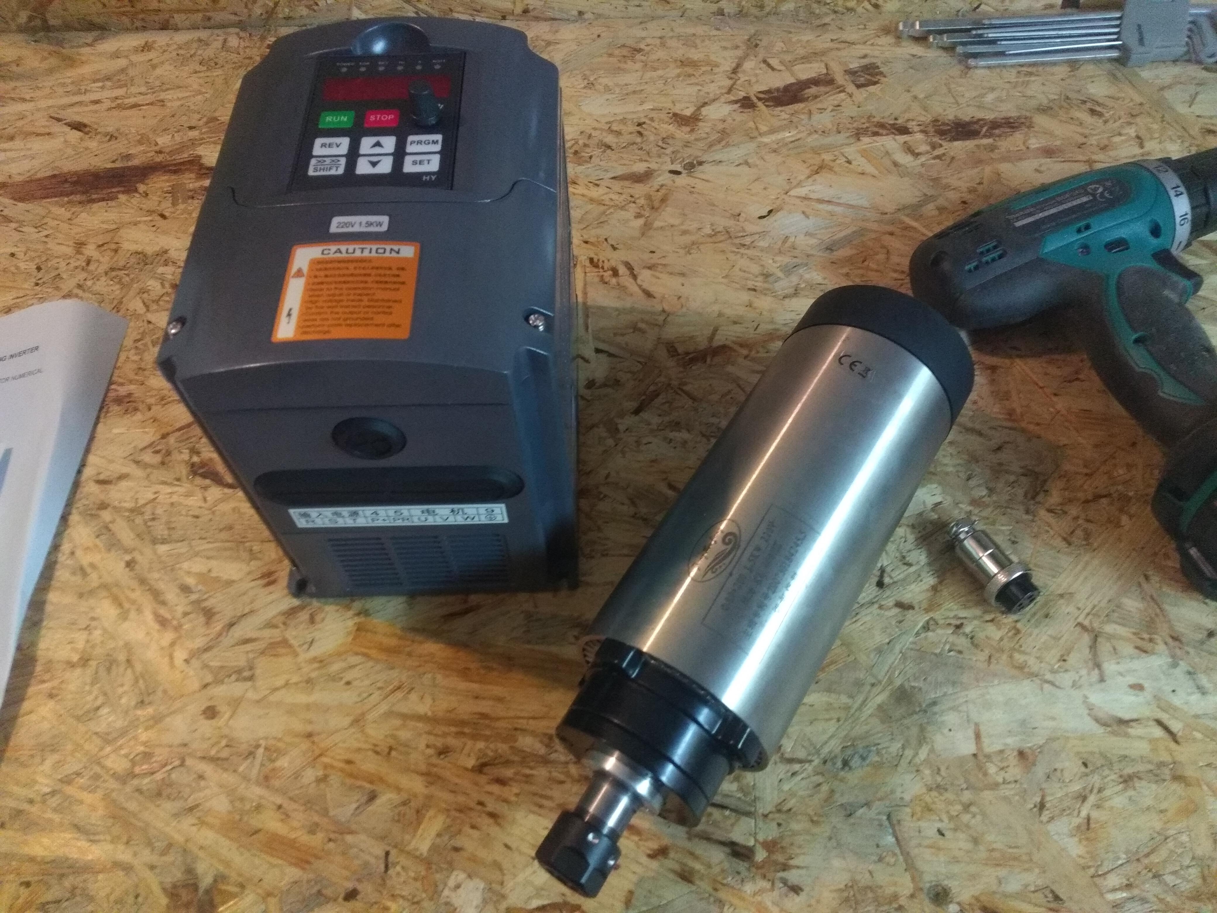
As the milling spindle, a common 1.5kW Chinese high frequency spindle with 20000RPM and ER16 collets is chosen. This spindle seems to be quite an appropriate size for this machine and it costs only about 250 Euros with an inverter included from ebay. Of course, you probably cannot expect years of lifetime under heavy load, but that is not what this project is about anyways. When the spindle arrived, the first thing I measured was the runout in the spindle cone with a dial indicator, and I was pleasantly surprised. The needle would move less than one hundredth of a millimeter, the smallest increment on my indicator. Now as far as spindle runout measurements go, this is by far not all that can be said about a spindle, but I figured it is a good start for a hobby project.
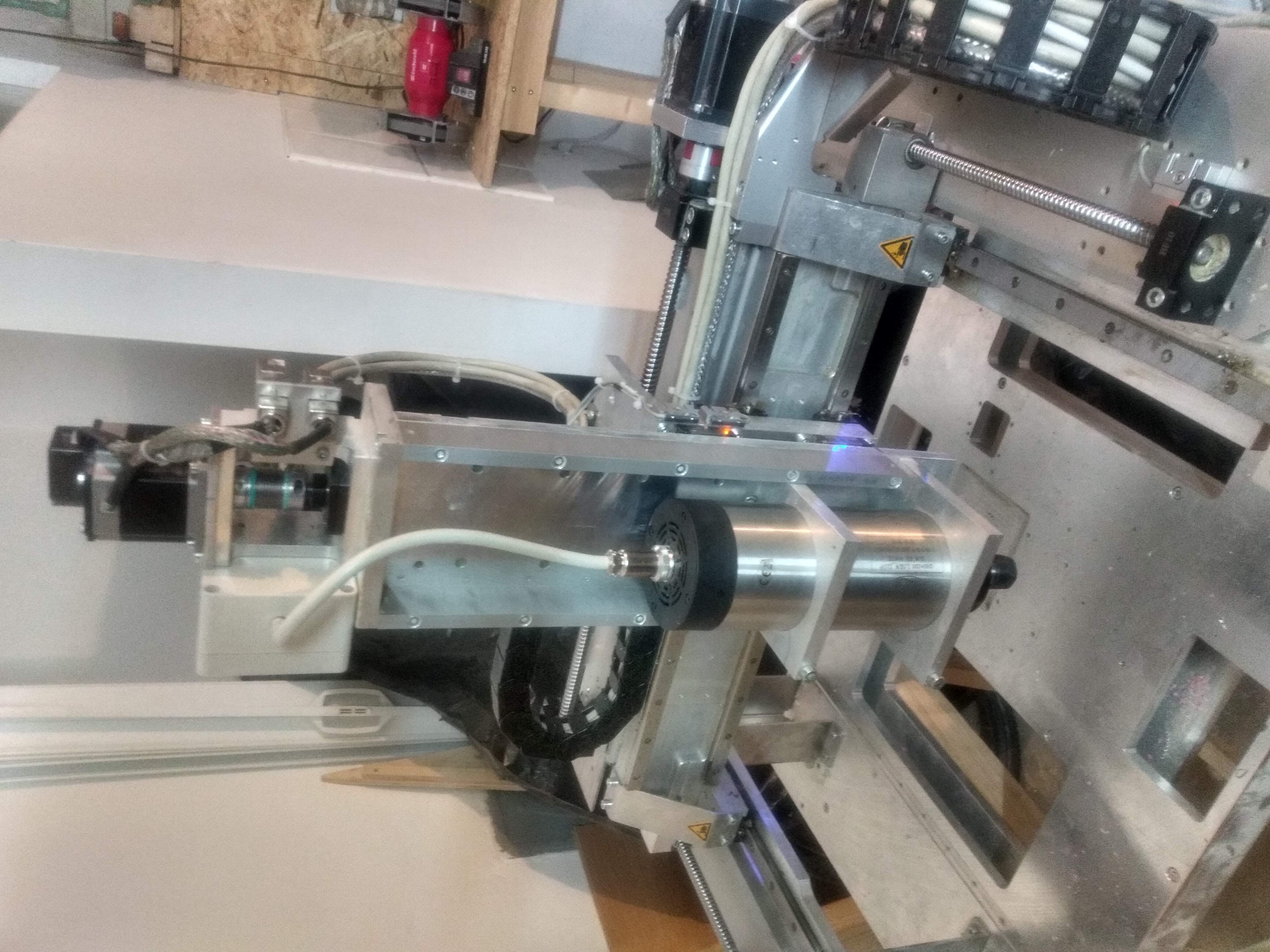
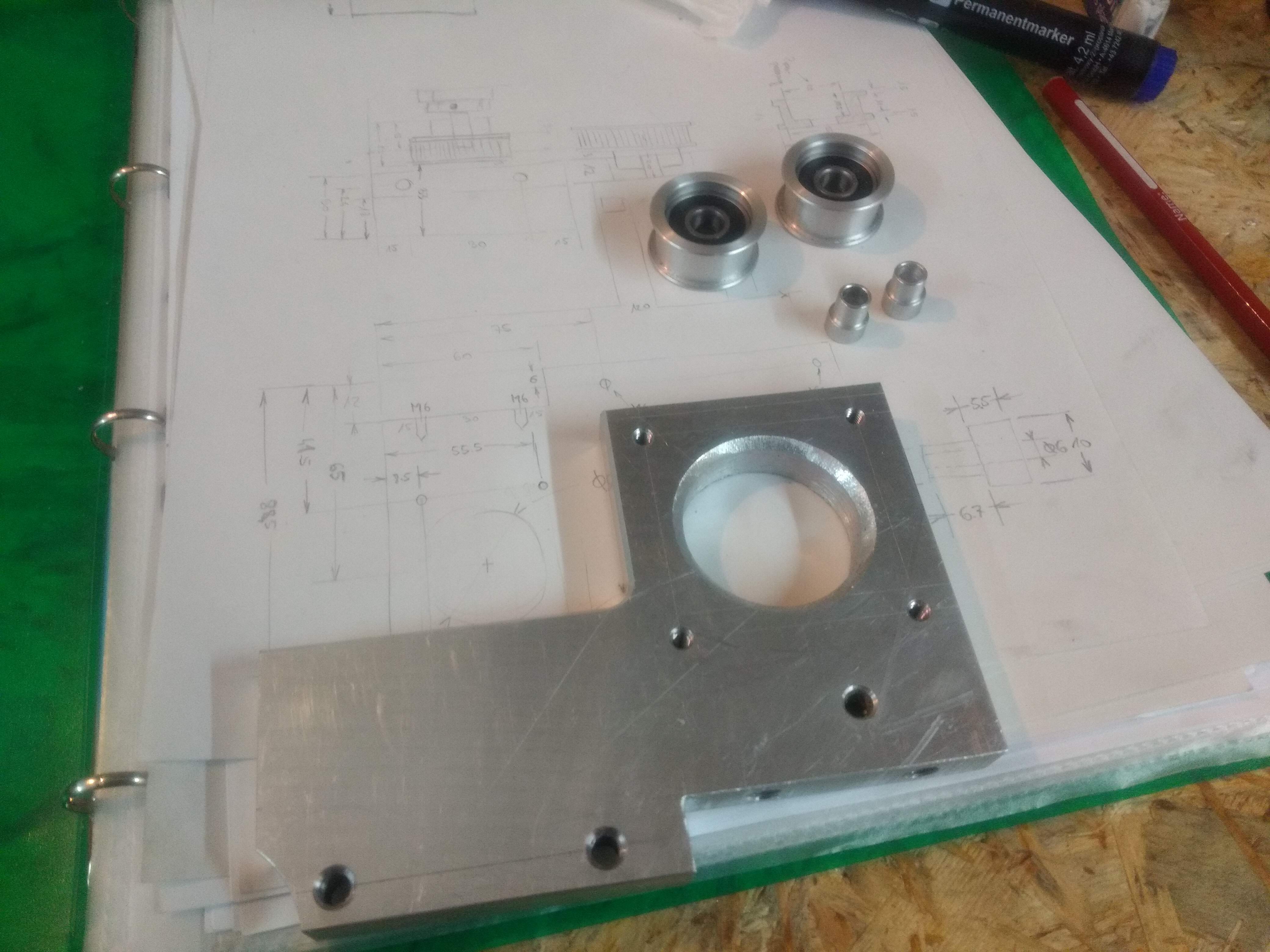
For mounting the spindle on the machine, two custom holding pieces are cut from flat aluminium stock and bored to size on my small lathe. The pieces are then drilled, tapped and slit with the bandsaw in a way that they can clamp the spindle body on the whole circumference. I know, there are aluminium spindle holders available on ebay for exactly this purpose, but those are very cumbersome and create more overhang of the spindle axis with regard to the machine rails, so in my understanding, the slim version shown is not only more elegant, but also stiffer.
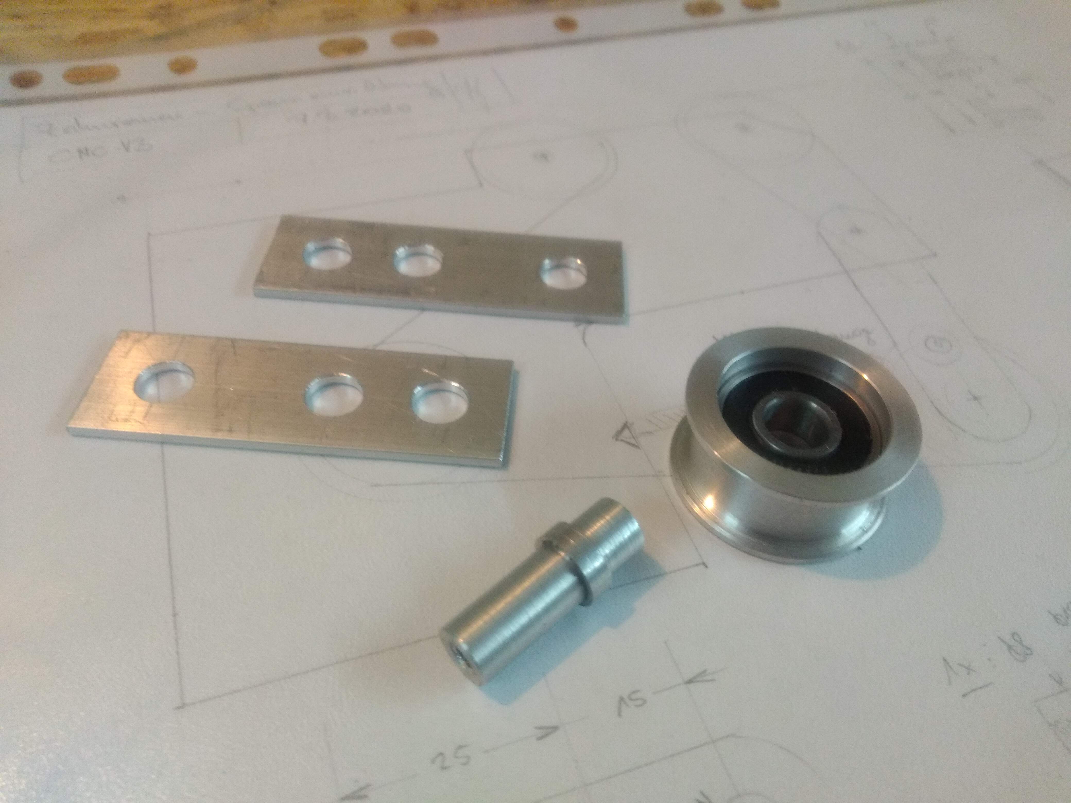
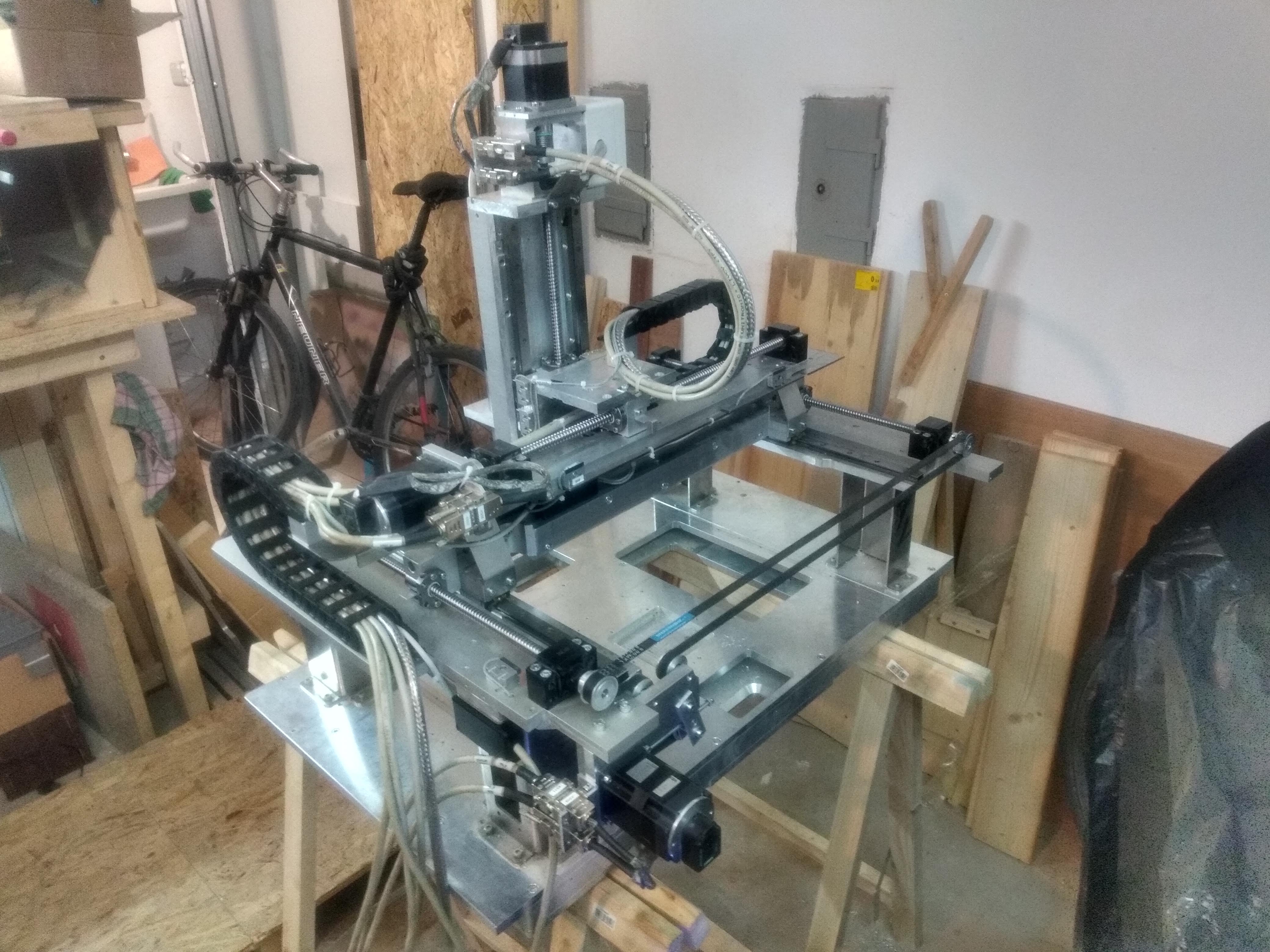
As already mentioned, the y-axis has two ballscrews, one on each side. Those need to be driven synchronously. Of course, you could configure LinuxCNC to lock two motors together, but why buy another motor when you can use a toothed belt and just connect them mechanically? That’s at least, what I thought. For this matter, a couple of aluminium parts are made to mount the stepper motor as well as to guide and tension the belt.
When assembled on the machine, I wondered for a moment if this could not have been achieved by a simpler solution, and maybe it can, but not that it is already finished and works nicely, why worry about it?
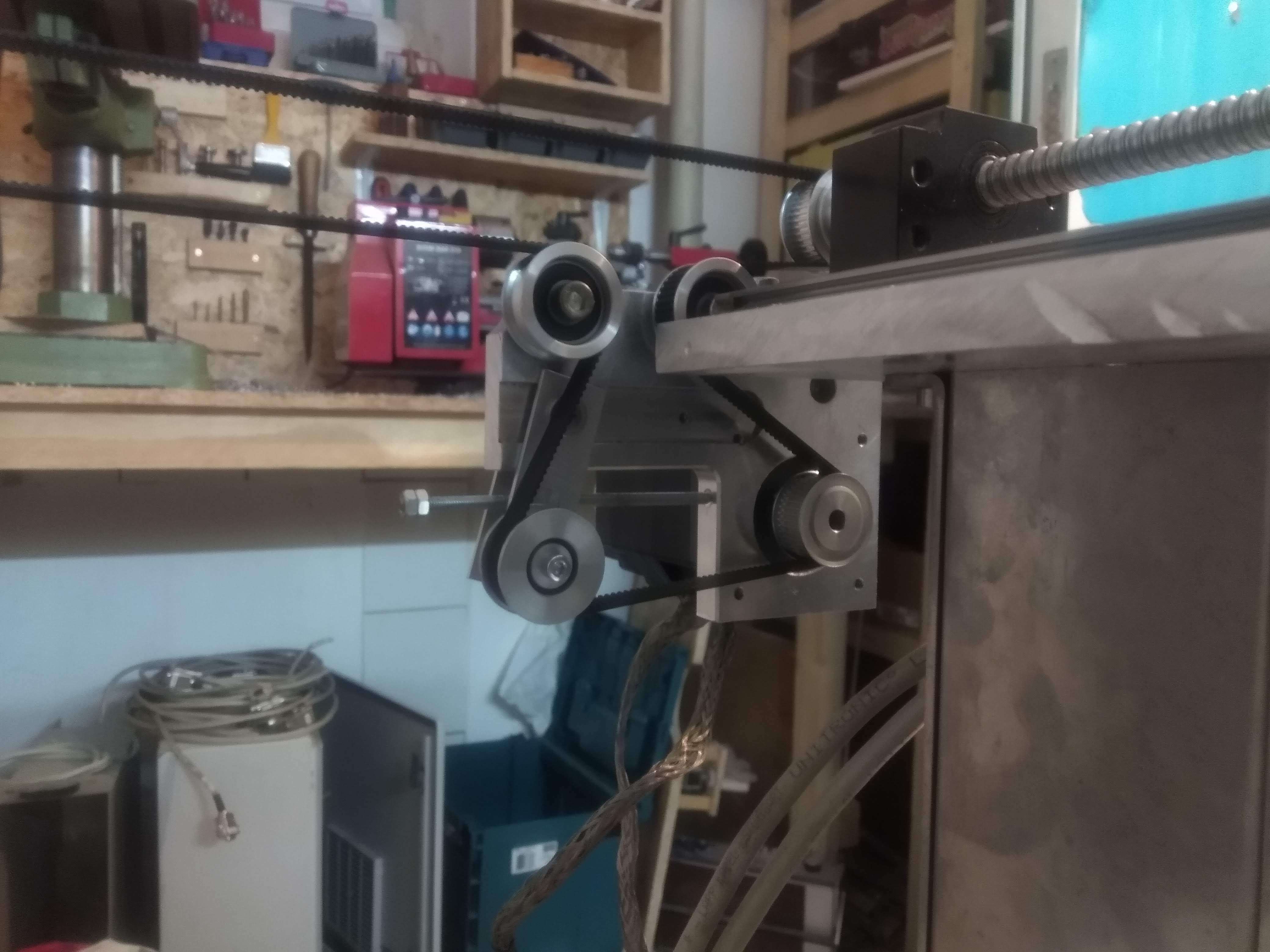
The following image shows the whole mechanism from the back, how it connects the two sides. Note that the fine adjustment of the screw positions can be made when loosening the setscrews that clamp the pulleys to the ballscrew shafts.
Now that the mechanics of the machine are basically done, it is time investigate the electronics and the control system in the next part.